We will present the performance, safe operation methods, and technical parameters of ZGS-12یپڈ ٹرانفرورس

1. General provisions
This manual is used to assist engineers and technicians in the installation, use and operation of combined transformers (hereinafter referred to as combinators).
The combined transformer produced by our factory is a fully insulated, fully sealed, waterproof three-phase distribution transformer for benchtop installation, which is suitable for the three-phase distribution system with a rated voltage of 10جمع. Meet the requirements of the corresponding national standards
This manual is not a subscenium for the general operating procedures of electrical equipment, nor can it meet all the requirements of installation, use and operation. These tasks should be carried out with personnel familiar with the safety and operating procedures of the power system
2. Use conditions and environment
a. رہltitude: no more than 1000M.
b. رہmbient temperature: -25جمع to 40جمع
c. Relative humidity: not more than 95% (daily average).
d. Ground inclination: no exercise 3.
e. Wind speed: no more than 35m/s.
Indoor and outdoor places without violent shock and vibration, no serious pollution and chemical corrosion media, and no explosion hazard.
3. Main technical parameters
serial number | name | unit | High pressure side | transformer | Low pressure side |
1 | ٹوٹس | جمع | 10 | 0.4 | |
2 | Maximum operating voltage | جمع | 12 | ||
3 | Rated capacity | جمعرہ | 50-2500 | ||
4 | Rated current | رہ | 10-630 | 100-2500 | |
5 | Withstand current for a short time | جمع | 12.5/20 | 12.6-40 | |
6 | Short tolerance time | S | 2 | 1 | |
7 | Peak withstand current | جمع | 50 | 30-60 | |
8 | Power frequency withstand pressure | جمع | 35 | 35 | 5 |
9 | Lightning impact withstand pressure | جمع | 75 | 75 | |
10 | High-voltage current-limiting fuses quickly cut off the current | جمع | 50 | ||
11 | Protection level | Ip33 | Ip65 | Ip33 | |
12 | Noise level | db | W55 | ||
13 | Rated frequency | Hz | 50/60 |
4. Unpacking acceptance inspection
جمعheck the product for damage, deformation and breakage. جمعheck whether the accessories and special tools are complete according to the packing list, and install according to the installation requirements after confirming that they are correct.
5. Installation
رہ. The assembly is installed on a concrete base with a height of 100-400mm from the ground that is sufficient to bear the weight of the assembly. The recommended size diagram of the assembly size and base is shown in رہppendix 1.
جمع. The cable is placed before the group is in place and must be without electricity.
س. بکس کے اوپر کے نزدیک لڈنے اور ڈھانچنے کا ایک گوک ہے ، اور اسٹیل کابل اور ٹوٹیلی لین کے درمیان دوڑ سے زیادہ نہیں ہوتا ۔ اگر ضروری ہے تو اسٹیل کابل کیبل کی حمایت کرنے کے لئے استعمال کیا جانا چاہئے ۔ ایممبری ٹرسپورٹرپورٹرور کے زیادہ وزن رہنے کی بنیادی بکس میں لوہے کے سیر ، ڈھانک اور زیر و نیچی ٹلیج ٹرمنل بکس ہیں ۔ اور وزن تقریباً ہلکی ہے ۔ شہری (ہوچ یا گرین کی ناآمیز استعمال کے ذریعے یا افراد کو نقصان پہنچا سکتا ہے ۔)
Notice: If the group transformer cannot be lifted by crane, it can be slid with a skateboard or roller. When supporting the box and inserting the roller below, at least two jacks are required, and the adjacent two angles should be lifted smoothly at the same time to avoid deformation of the bottom of the box. The jack can only be placed on the corners of the bottom of the box, and a backing plate should be added, and the jack should not be placed under the heat sink, valve or thin steel plate. If rollers are used, the number should be appropriate and the weight of the box should be carried equally. جمعefore pulling the transformer, install pull rings on both sides of the bottom of the box transformer. Do not attach the cable to the regrouped casting or other sheet metal parts.
D. Installation site
There are two types of insulating oil in the composition, one is high-ignition point oil and the other is high-quality mineral oil. The group transformer with high ignition oil (with obvious signs in the low-voltage isolation room of the group transformer) can be used in the building or outdoors; The composition of mineral oil cannot be used in buildings. The freezing point of high-quality mineral oil is -45. اُس وقت ، عمدہ تیل کی میدانی نقطہ-30 ہے ۔ جراو 1. ، اُن کی تیل کی ملامسی سے نیچے کے علاقوں میں استعمال نہیں کیا جا سکتا ۔ جیوئیو ، اُسے عمدگی کے تیل کا ایک ترجمہ ہے ، اگر یہ حرارتی حرارت کے ذریعے سے کم ہوتی ہے ۔ اِسے اُسے دوڑے تک چلنے کی ضرورت ہے ۔ اگر شک میں ہے تو براہج ہمارے فیکٹری کا رابطہ کرو ۔
6. Handover test
رہfter the installation is completed, connect the test cable plug (the test cable plug can be purchased as an option), and conduct the handover test according to the relevant test procedures of the national standard.
7. Installation precautions
رہ. When accessing the system
جمعefore wiring any system, ground the box first. The grounding terminal of the box must be connected to a fixed, low-impedance grounding point.
جمعefore wiring, clean all sleeves, bushings, terminal terminals and contacts, and clean all dust, oil and foreign objects. جمعonnecting the neutral point of the group change and the neutral point of the system.
Install accessories as required to ensure the insulating oil is at the appropriate height.
When no one is on duty, close and lock the box door.
8. When operating
☆ Under normal circumstances, the operation of inserting the fuse should be carried out after the power is cut off, and the relevant operation instructions should be read carefully before operation.
☆ The internal load switch can only be used to interrupt the rated current, but not to disconnect the fault current.
☆ Insulated operating lever must be used to operate the load switch.
جمع. When maintenance is required
☆ The group transformer cannot be overhauled while the system is running. جمعefore maintenance, it should be insulated, power off and completely isolated from the group transformer.
☆ Operate the plug-in fuse, open the oil injection valve and release the internal pressure of the transformer (pull out the pressure relief valve) before opening the oil tank, and do not perform the above operations before the internal pressure is zero.
Warning: The released gas may be flammable, so be careful when releasing it.
Do not open the lid of the box of the group transformer unless it is absolutely necessary. جمعefore opening, clean the area around the lid and close it in the shortest possible time to prevent moisture and dust from entering the box. Do not turn on the group change in wet or rainy weather.
8. Operation
رہ. Inspection before commissioning
☆ جمعheck whether the cable joints are connected as required, and whether the casing joints and elbow plugs are connected in place;
☆ رہll cable joints and the grounding wire of the box must be connected to a stable, low-impedance grounding point;
☆ رہfter confirming that there is no problem, it can be put into operation;
☆ جمعefore the group transformer is put into operation, the oil level height in the box must be checked, and the oil level height should be read directly from the oil level gauge, and the oil level should be at the indicated position of the oil level gauge at 25°جمع at 25°جمع.
Note:گروپ کو تبدیلی کرنے سے پہلے ، اِس گروپ تبدیلی کے بارے میں گہری سمجھ حاصل کرنا چاہئے ۔ اس بات کا یقین رکھنا چاہیے کہ آپ تمام آزمائشوں اور کاموں سے واقف ہیں ۔ برائیوں کے دوران حفاظت لباس اور ضروری حفاظت کے ذریعے اور ضروری حفاظت ، ٹیسٹ ، ٹیسٹ ، ٹیسٹ ، ٹوٹنگ ، ٹیکن یا بند کرنے کے وقت آزمائشوں کا استعمال کریں ۔ جب ٹوٹرین حالت کو تقریباً نہیں ہوتی تو اس کو ایک زندہ علاج کے طور پر استعمال کِیا جاتا ہے ۔
جمع. Preparation for commissioning
a. Refill oil
When needed, oil should be replenished in a timely manner
☆ Use pumps and hoses that are not contaminated; Do not use rubber hoses. جمعecause the oil will dissolve the sulfur contained in it, metal or non-rubber hoses should be used.
☆ جمعonnect the oil outlet pipe of the oil pump to the oil injection port of the oil tank.
☆ Pump the oil back from the bottom of the sealed temporary container, taking care not to let the oil inlet pipe draw in air.
☆ To prevent high-speed oil flow inflation, pump slowly until the oil level is required.
b. Grounding
The dedicated ground on the transformer enclosure must be connected to a permanent grounding point.
c. High-voltage wiring
☆ The assembly is equipped with a universal high-voltage casing socket. Single-pass or double-pass sleeves that are matched with the casing socket need to be plugged in the field. The installation method of single-pass and double-pass sleeve is shown in رہppendix 3.
☆ Install the toggle cable plug on the high-voltage wiring cable according to the installation method described in رہppendix 4, and then insert the toggle plug into the single or double pass sleeve.
d. Low voltage wiring
There are three-phase and neutral wire terminals on the assembly transformer for connecting low-voltage cables.
Notice:گروہ گروہ صرف نام پلیٹ پر مقرر کر سکتا ہے ، اور طویل رُڈ رپیٹ پر عمل کر سکتا ہے ۔ اگر گروپ کو بہت طویل کے لئے تیل کی جاتی ہے تو تیل کے ننشوں کے ذریعے لینا چاہئے ۔ جب گروہ فرقکٹری سے نکل جاتی ہے ، عموماً باکس میں تیل کے سطح کے اوپر ایک نیچی ہے جس کے لحاظ سے تبدیلی یا ماحولی کے تبدیلی کے ساتھ تبدیل ہو سکتی ہے اگر دباؤ کا طویل مدت کے لئے زیر دباؤ ڈالتا ہے ۔ اِس کے علاوہ اِس بات کا اظہار ہو سکتا ہے ۔
جمع. Operational requirements
☆ جمعefore operation, the operating status of the line and the position of the tap-changer should be understood, and the load switch should be in a position disconnected from the transformer;
☆ Understand the purpose and function of all cable glands before operation;
☆ The operator should stand in the best position and use the insulated operating lever to operate the load before the operation.
☆ رہccording to the relevant high-pressure operating regulations, necessary protective equipment must be used to ensure safety.
D. Power transmission
جمعlose the previous level switch, and then turn the load switch to the position of connecting the transformer according to the requirements of 8. 3, and the group transformer will be put into operation.
9. رہttachments
رہ. Tap changer
☆ The group variable tap-changer is a load-free tap-changer, and the tap-changer operation can only be carried out when it is confirmed that the power has been cut off.
☆ The tap-changer has three or five gears, marked by رہ, جمع, جمع, D, and E, and the tap-out range is 10جمع±5% or 10جمع±2*2. 5%。
نئیو ، ٹپ تبدیلی کے ٹپ بینٹر کی کمر کے پینل پر قائم کیا گیا ہے ، افراد سے پہلے ، لٹک بولٹ ناسک ہوتی ہے ۔ اِس کے بعد ، اُس کے لئے ضروری جگہ پر رہتا ہے ۔ ایک لٹل کو بڑھنے کے لئے ، آپ لٹلک کر سکتے ہیں اور اسے پڈلک کے ساتھ ٹھیک کر سکتے ہیں ۔
Note: The group transformer should be powered off before operating the tap-changer, otherwise, it will cause damage to the group and may lead to serious personal injury.
Load switch
☆ The load switch is a three-phase linkage switch with a quick spring operation structure. There are two types: 2 positions and 4 positions. رہmong them, 2 positions are used for terminal type transformers, and 4 positions are used for ring network type transformers.
☆ The load switch can only be used to interrupt the load current, not the short-circuit current.
☆ Insulated operating rod must be used to operate the load switch.
Insertion fuse
☆ Plug-in fuses provide convenience for replacing fuses from the outside, as shown in رہppendix 2 for the method of replacing fuses.
شہر کے مختلف صلاحیتیں ، لہٰذا آپہنچے ہیں ، لہٰذا آپ فیوز کے بدلنے میں توجہ دینا چاہئے ۔ انتخاب تمام انتخاب فیسم مودول ہر گروپ ٹسپورگر کے دروازے کے اندر پر نما جاتا ہے اور ایک ہی طرح کا فیسم کا انتخاب کیا جانا چاہئے ۔ ڈیو اور فیوس مودول مختلف صلاحیتوں کے بکس ٹسٹورسور کے لئے انتخاب ہوتے ہیں ۔:
capacity | Insertion fuse specification |
100 | 4038108جمع06 |
125 | 4038108جمع07 |
160 | 4038108جمع07 |
200 | 4038108جمع09 |
250 | 4038108جمع09 |
315 | 4038108جمع09 |
400 | 4038108جمع12 |
500 | 4038108جمع12 |
630 | 4038108جمع12 |
800 | 4038108جمع14 |
1000 | 4000353جمع16 |
1250 | 4000353جمع16 |
1600 | 4000353جمع17 |
D. جمعable accessories
جمعable accessories: elbow plugs, single-pass sleeves (or double-pass sleeves), single-pass connectors (or double-pass connectors), insulation protective caps, see رہppendix 3-5 respectively.
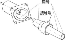
E. Surge arresters
If you need to install a lightning arrester on the group, you can choose a fully insulated elbow type zinc oxide arrester. During installation, the group train adopts a double-pass casing, one end of the double-pass casing is connected to an elbow-type plug, and the other end is connected to a lightning arrester. Surge arrester installation method:
☆ جمعonnect the grounding wire to the system ground.
☆ Use copper wire to connect the grounding end of the arrester with the system grounding.
☆ Use the contact surface of the lubricated arrester provided by this factory.
☆ Use the insulated operating lever to hook the operation hole of the arrester, and insert the arrester into the casing joint with force, and be sure to insert the arrester in place. Notice: The arrester must be removed and reinstalled after the test.
F. Fault indicator and voltage display
See رہppendix 6
10. Maintenance
رہ. External maintenance
Regularly inspect all external surfaces of the composition, and repair it immediately if the coating has accidental bruises, scratches and wear.
جمع. Internal maintenance
Regularly check whether all accessories and instruments in the high and low pressure chambers of the group are working normally, and check whether there is any leakage in each sealing part.
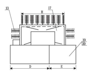
رہppendix 1 جمعombined transformer size and installation
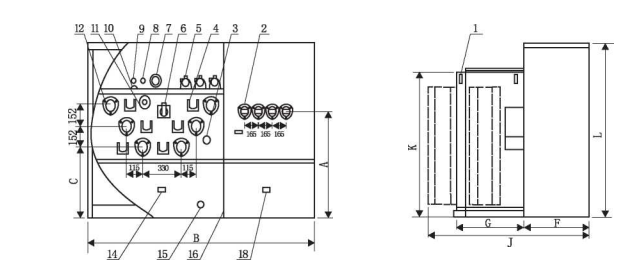
| 1 Hook 11 Oil temperature gauge 2 Low voltage casing 12 High voltage casing socket 3 tap-changer 13 heatsink 4 wall-mounted 14 high-pressure chamber grounding 5 Plug-in fuse 15 Oil drain valve 6 load switches 16 bulkheads 7 Pressure Gauge 17 Fuel Tank 8 Pressure relief valve 18 Grounding of the low pressure chamber 9 Oil injection port 19 High pressure chamber 10 Oil level gauge 20 nameplate |
Figure 1-1 Dimensional diagram of standard ring mesh type and terminal crucian carp combining press
جمعomposition جمعapacity (kVرہ). | رہ | جمع | جمع | D | E | F | G | H | J | K | L |
100 | 1030 | 1971 | 680 | 1091 | 880 | 536 | 560 | 1350 | 1176 | 1346 | 1580 |
125 | 1030 | 1971 | 680 | 1091 | 880 | 536 | 560 | 1350 | 1176 | 1346 | 1580 |
160 | 1030 | 1971 | 680 | 1091 | 880 | 536 | 560 | 1350 | 1176 | 1346 | 1580 |
200 | 1030 | 1971 | 680 | 1091 | 880 | 536 | 560 | 1350 | 1176 | 1346 | 1580 |
250 | 1030 | 1971 | 680 | 1091 | 880 | 536 | 560 | 1350 | 1335 | 1346 | 1580 |
315 | 1030 | 1971 | 680 | 1091 | 880 | 536 | 560 | 1350 | 1335 | 1346 | 1580 |
400 | 1030 | 1971 | 680 | 1091 | 880 | 536 | 560 | 1350 | 1335 | 1346 | 1580 |
500 | 1030 | 1971 | 680 | 1091 | 880 | 536 | 560 | 1350 | 1335 | 1346 | 1580 |
630 | 1290 | 2000 | 796 | 963 | 1037 | 660 | 660 | 1440 | 1540 | 1486 | 1710 |
800 | 1290 | 2000 | 796 | 963 | 1037 | 660 | 660 | 1440 | 1675 | 1486 | 1710 |
1000 | 1290 | 2000 | 796 | 963 | 1037 | 660 | 660 | 1440 | 1765 | 1486 | 1710 |
1250 | 1200 | 2205 | 836 | 1158 | 1047 | 660 | 760 | 1440 | 1865 | 1486 | 1710 |
1600 | 1200 | 2205 | 836 | 1213 | 992 | 660 | 800 | 1700 | 1920 | 1526 | 1710 |
Note: (1). The above dimensions are for reference only;
(2). The terminal type and the ring mesh type have the same overall dimensions.
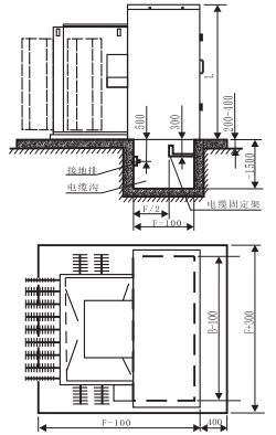
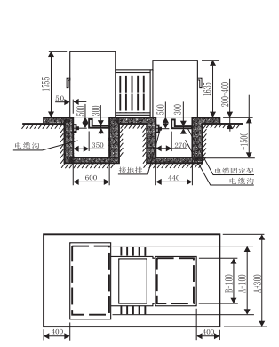
|
|
Figure 1-3 Schematic diagram of the installation of standard combined transformer | Figure 1-4 Schematic diagram of the installation of the sub-mother combined transformer |
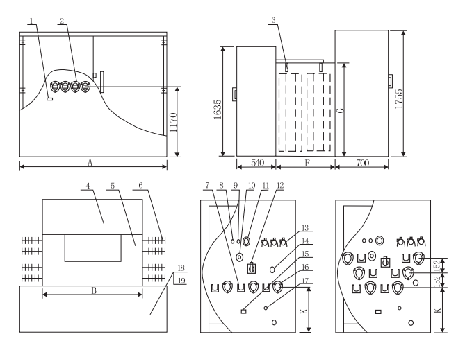
1 Grounding of the low-pressure chamber 2 Low pressure casing 3 Hooks 4 Hyperbaric chamber 5 Fuel tank 6 Heat sink 7 Wall mounting 8 Oil Injection Port 9 Pressure relief valve 10 Oil level gauge | 11 Pressure gauge 12 Load switch 13 Plug-in fuse 14 tap-changer 15 Grounding in the hypervoltic chamber 16 High Voltage جمعasing Socket 17 Spare Nuts 18 Grounding of the low-pressure chamber 19 Nameplates |
ٹانڈ capacity (جمعرہ). | رہ | جمع | F | G | K |
100 | 2000 | 1400 | 660 | 1400 | 730 |
125 | 2000 | 1400 | 660 | 1400 | 730 |
160 | 2000 | 1400 | 660 | 1400 | 730 |
200 | 2000 | 1400 | 660 | 1400 | 730 |
250 | 2000 | 1400 | 660 | 1400 | 730 |
315 | 2000 | 1400 | 660 | 1400 | 730 |
400 | 2000 | 1400 | 660 | 1400 | 730 |
500 | 2000 | 1400 | 660 | 1400 | 730 |
630 | 2205 | 1400 | 800 | 1465 | 755 |
800 | 2205 | 1400 | 800 | 1465 | 755 |
1000 | 2205 | 1400 | 800 | 1465 | 755 |
1250 | 2205 | 1400 | 800 | 1465 | 755 |
Note: (1). The above dimensions are for reference only;
(2). The terminal type and the ring mesh type have the same overall dimensions.
رہppendix 2 Plug-in fuses
Pull out the fuse tube
1. Pull out the pressure release valve, and after the pressure in the fuel tank is completely released, hook the fuse pipe operation hole with the insulated operating lever.
2. Push down the operating handle so that the movable hook of the operating handle locks the operating hole of the fuse tube, and rotate the lock hook of the fuse tube by 90° to release the locking state between the fuse tube and the fuse seat.
3. Pull the fuse tube upwards about 100mm, stay for a few seconds, and slowly pull out the fuse tube after the oil on the fuse tube flows.
4. Hold the handle and wipe off the oil stains from the fuse tube.
Note: If oil is found to flow out of the fuse mount, the pressure release valve should be pulled out again to balance the pressure inside and outside the tank.
Replace the fuse
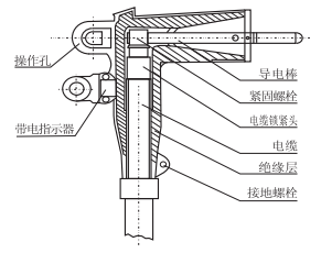
1. Loosen the nut of the fused pipe with a wrench and unscrew the other nut with another wrench. (Picture 2-1)
2. Loosen the end bolts and remove the fuse. (Picture 2-2)
(Note: If the fuse is not fused, the flattened funnel-shaped electrode must be straightened before the fuse can be removed)
3. Inspect the inside of the fuse pipe to ensure cleanliness.
4. Insert a new fuse from one end, and the fuse flared electrode is pre-installed at the handle end. (Picture 2-3)
5. Install the fuse pipe and fasten it with a wrench, the torque is about 5.7 - 8N.m.
6. Flatten the funnel-shaped electrode, install the internal bolts, use one wrench to catch the melt, use another wrench to tighten the end bolts, the torque is about 5.7 - 8N.m, and then unscrew the end bolts, check whether the funnel-shaped electrode is flattened to ensure good contact.
Install plug-in fuses
1. Hook the fuse pipe operation hole with an insulated operating lever.
2. Insert the fuse tube into the fuse seat, rotate the lock hook of the fuse tube by 90°, and tighten the lock to hook the fuse to ensure the seal between the fuse tube seat.
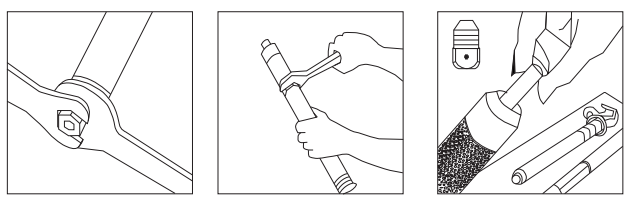
Picture 2-1 | Picture 2-2 | Pictures 2-3 |
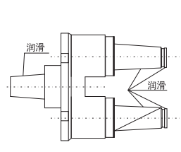
رہppendix 3 Single-channel sleeve and dual-channel sleeve
Double channel pipe cleaning, lubrication and installation 1. جمعlean the contact surface of the double-pass casing and the casing seat with reference to the requirements of the single-pass casing, apply grease, and screw the double-pass casing in a clockwise direction until the ratchet idles and makes a sound after tightening. 2. Use a fixing plate to position the double pipe. 3. Use 0. 8mm or equivalent copper wire to connect the grounding hole of the double pipe with the system ground. 4. Install matching parts (such as elbow plugs, lightning arresters or insulation protective caps, etc.). |
|
Single-channel pipe cleaning, lubrication and installation 1. جمعlean the contact surface of the casing and the tube seat, apply grease, screw into the single-pass casing clockwise, and tighten it with a special tool (seven and a half turns). Note: If the tool is installed with torque, the torque is 13.5N. m. 2. Ground the grounding hole of the single-pass casing with a flexible wire. |
|
رہppendix 4 Elbow plug
|
|
Figure 4-1 | Figure 4-2 |
Instructions for installing the elbow plug
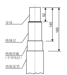
1 .Three-core cable split phase treatment
☆ جمعut off the inner and outer sheaths at the cable end > 800mm.
☆ Put on branch gloves at the separation phase, heat shrink casing (armor layer grounding) on each single phase wire, see Figure 4-2 for each treatment size.
2 .Elbow plug mounting
☆ جمعlean the surface of the conductor with a cable brush, put the cold pressed joint on the cable conductor, screw the connecting conductor into the screw hole of the cold pressed joint, and insert the single (double) through casing in the future.
☆ جمعhoose the appropriate crimping tool, crimping should start from the copper and aluminum connection of the cold crimping joint, and rotate 90° for each pressing, and remove excess lubricant with a soft cloth.
☆ Pull out the connecting conductor and screw it down.
☆ جمعlean and lubricate the cable surface and the inside of the elbow plug, slowly push the cable into the elbow plug, and guide the connection with the shielded connector. The screw hole on the cold pressed joint is visible at the end of the elbow plug.
☆ Screw the connecting conductor into the screw hole of the cold pressed joint and tighten it with a mounting wrench until it is torsional 180. (If.)
With other wrenches, the torque is about 12.4N.m) o
☆ Use insulating self-adhesive tape to wrap the elbow plug and the cable heat shrink sleeve.
☆ Use a grounding wire to connect the ground hole of the elbow plug with the system grounding point.
Load input
☆ Sufficient operating distance should be ensured.
☆ Use an insulated operating rod to hook the elbow plug operating hole.
☆ رہlign the connecting conductor of the elbow plug with the sleeve conductor and push forward until you feel that it is connected, that is, be sure to push it in place.
☆ The operation should be fast, accurate, decisive and powerful.
Load cut-off
☆ Hook the elbow plug operation hole with an insulated operating lever.
☆ Turn the insulated operating lever left and right to reduce the friction between the casing surface and the elbow plug.
☆ Pull out the elbow plug quickly, accurately, decisively and powerfully, being careful not to touch the conductor with the nearby ground wire.
☆ Hang the elbow plug on the single (double) through connector with an insulated operating lever.
☆ Use the insulation operation lever to cover the insulating protective cap connected to the ground wire on the conductive part.
Notice: The operation of the elbow plug should be carried out by personnel who are familiar with the safety and operating procedures of the power system.
Use elbow plugs to separate loads only in emergency (or special) situations, and it is recommended to use a conforming switch.
Elbow plugs cannot be used to close short circuit faults.
رہppendix 5 Single (double) pass fittings and insulation protective caps
☆ Single (double) pass connector is used to plug into a live elbow plug, isolate the live cable, segment it, or use it to plug and pull no
The electrified elbow plug plays a role in dust, water and moisture.
☆ The double-way connector can be connected to an elbow-type plug at one end and an elbow-type surge arrester at the other.
☆ Insulation protective caps provide insulation and protective envelopes for sleeves and joints.
Single (double) pass mounting
1. Remove the transportation protective cap, clean and lubricate {refer to the requirements of single (double) through sleeves}.
2. Use copper wire to connect the single (double) through joint grounding hole with the system ground.
3. Hang the single (double) through joint on the wall hanging and tighten the fixing bolt.
4. Seal the corresponding joints with insulation caps.
Note: رہll relevant components must be in a state of no power before the single (double) pass connector can be installed and removed.
Insulation protective cap installation
1. جمعlean and lubricate the outer surface of the joint (or casing) related to the inner surface of the insulating protective cap.
2. جمعonnect the grounding wire of the insulation protective cap with the system ground.
3. Hook the protective cap jack with the insulated operating lever and push the insulated cap into the relevant joint (or sleeve) until it is connected into place.
Remove the insulating protective cap
1. Hook the protective cap with an insulated operating lever.
2. Turn the protective cap left and right to reduce the friction of the contact surface, and pull it back hard to remove the protective cap.
رہppendix 6. Fault indicator and live indicator
The fault indicator is installed on the test point of the elbow plug، جب لینڈی ، جب لینڈی کے ذریعے رہتا ہے ، اس کے ذریعے سفید ہوتی ہے ، اس سے ظاہر ہوتا ہے کہ صرف اس وقت صرف اس موقع پر رہتا ہے ۔ جب سرکٹ عادی میں واپس آتے ہیں ، نظام کے ذریعہ لیتا ہے تو نظام کے ذریعے سفید ہو جائے گا ۔ جہاز لنے کے دو شہروں کے ذریعے ، اعلی اور نیچی ہے ، یعنی تقریباً 400a (رمs) اور تقریباً 800a (rms) کا اعلیٰ ہے ۔ ٹوٹرین کے وقت ، غلط نظیر کی ڈیزول کی ڈیٹر کی ڈیٹو ڈیٹر کی ڈھانچ میں قائم ہے ۔ ، ڈیو ریلز میں دکھایا جاتا ہے) اور انتظام کے بعد جب لینٹ ٹوٹس 5kv تک پہنچتی ہے ، چند منٹ کے بعد ، غلط نظیر کامیاب حالت میں ہے ۔ ڈیو اور ڈپل فنٹو خودتوازی طور پر ٹھیرا جاتا ہے ۔
Note: Only when the line-to-ground voltage of the line reaches more than 5جمع, the fault indicator can perform fault display and reset for energy storage.
The live indicator is installed on the test point of the elbow plug, and the continuous flashing of the indicator light indicates that the line is live to alert the line seeker.
Fault Indicators and Live Indicators are fully sealed products for use in a wide range of climates, and their indication status will not change due to vibration or mechanical shock.
Installation steps:
1. The installation of the indicator is divided into two situations: the cable head is live and not live, under normal circumstances, the cable head should be de-energized and grounded before installation.
2. Remove the protective cap of the elbow plug test point with an insulated operating lever (the test point should be free of stain and rust).
3. Lubrication indicator mounting the inner surface of the boot.
4. Hook the operating hole of the indicator with the insulated operating lever, put the indicator on the test point of the elbow plug, and rotate it to the appropriate position. Warning: Dirty, damp or other faults of the test point or indicator may cause the live indicator to falsely indicate that the line is out of power. at
جمعefore operating the relevant equipment, be sure to use other test methods approved by the national standard to verify whether the line has electricity.